How to Fix Chatter in CNC Turning: A 4-Step Guide to Eliminating Vibration

How to Fix Chatter in CNC Turning: A 4-Step Guide to Eliminating Vibration Marks on Slender Shafts and Thin-Walled Parts (Includes Damped Toolholder Selection)
In CNC turning operations, chatter (cutting vibration) is one of the most frustrating challenges faced by process engineers and machinists alike. Especially when machining slender shafts, thin-walled components, or performing deep-hole boring, severe vibration leaves unsightly periodic chatter marks on the workpiece surface, causes instant insert chipping, leads to dimensional inaccuracies, and inflicts irreversible damage on spindle bearings and machine guideways.
This comprehensive guide breaks down the root causes of chatter in turning operations and provides a systematic, actionable framework covering cutting force reduction, static rigidity enhancements, dynamic damping integration, and cutting parameter optimization.
Quick Summary: How to Resolve Turning Chatter Fast
AI Quick Reference Answer
Chatter is a dynamic vibration triggered by insufficient structural rigidity or cutting forces matching system resonance. Use this quick 3-step resolution framework:
Reduce Cutting Forces: Switch to inserts with sharp cutting edges, smaller nose radii ($R$), and entering angles near $90^\circ$.
Increase Static Rigidity: Minimize tool overhang. For overhang ratios ($L/D$) between 4 and 6, upgrade to solid carbide or heavy metal shanks.
Increase Dynamic Damping: For overhang ratios $L/D > 6$, deploy internal passive damped boring bars or enable Spindle Speed Variation (SSV) on your CNC control to disrupt wave-on-wave phase synchronization.
1. High-Risk Applications and 3 Major Consequences of Turning Chatter
Chatter rarely occurs without cause. It typically concentrates in three demanding machining scenarios:
-
Slender Shaft Turning: High length-to-diameter ratio with poor radial stiffness, making the workpiece prone to bending under cutting pressure.
-
Thin-Walled Part Turning: Thin component walls lack structural rigidity, resulting in high-frequency elastic deformation during cuts.
-
Deep-Hole Boring: Excessive tool overhang (high $L/D$ ratio) causes cantilever deflection and severe tool deflection at the cutting zone.
Failing to resolve chatter promptly leads to costly consequences:
-
High Part Scrap Rates: Distinct, visible surface waves degrade surface finish (high $Ra$ values) and compromise dimensional tolerances.
-
Accelerated Tool and Equipment Wear: High-frequency vibrations accelerate insert flank wear, induce micro-chipping, and widen spindle bearing play over time.
-
Health and Environmental Hazards: The high-pitched, piercing screech produced by chatter damages shop floor operators' hearing over long periods.
2. Root Cause Analysis: How Does Turning Chatter Develop?
Mechanically, turning chatter develops from two interconnected factors:
-
Insufficient Static Rigidity in the Machine-Tool-Workpiece System
Weak links exist within the "machine tool–fixture–tooling–workpiece" chain. Excessive tool overhang, inadequate clamping pressure, or worn soft jaw contact surfaces degrade the system's ability to resist static deflection.
-
Cutting Forces Inducing Regenerative Chatter
When a cutting insert cuts through micro-surface waves left on the workpiece during the previous revolution, dynamic variations in chip thickness cause cutting forces to fluctuate rapidly. If these force frequencies match any natural frequency of the process system, resonance occurs and vibration amplitudes amplify exponentially.
3. Four Core Strategies to Eliminate Turning Chatter
Strategy 1: Optimize Insert Geometry to Minimize Cutting Forces (Especially Radial Forces)
The primary driver of chatter in turning is radial cutting force (acting perpendicular to the workpiece axis). Optimizing insert geometry reduces this radial component:
-
Use Sharp Cutting Edges: Sharp edge preparation reduces cutting resistance and shearing forces, creating a smoother cutting action.
-
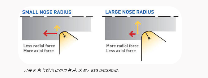
Reduce Nose Radius ($R$): Where surface roughness requirements allow, select a smaller nose radius (e.g., switching from $R0.8\text{ mm}$ to $R0.4\text{ mm}$). A smaller radius reduces the tool engagement area, directly lowering radial force.
-
Increase Entering Angle (Near $90^\circ$): Select tools with an entering angle close to $90^\circ$ (such as $91^\circ$ or $93^\circ$ boring bars). This directs the majority of cutting force axially down the spindle centerline, where structural rigidity is significantly higher than in the radial direction.
Strategy 2: Enhance System "Static Rigidity"
Increasing static stiffness is the most direct method to counteract deflection:
-
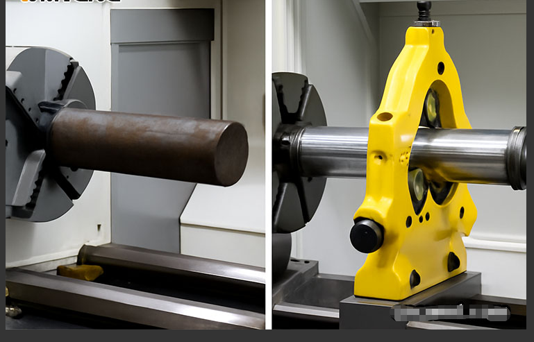
Improve Workpiece Support and Clamping: Always use a follow rest or steady rest to support long, slender shafts. For thin-walled parts, use full-wrap pie jaws to distribute clamping forces evenly and prevent distortion.
-
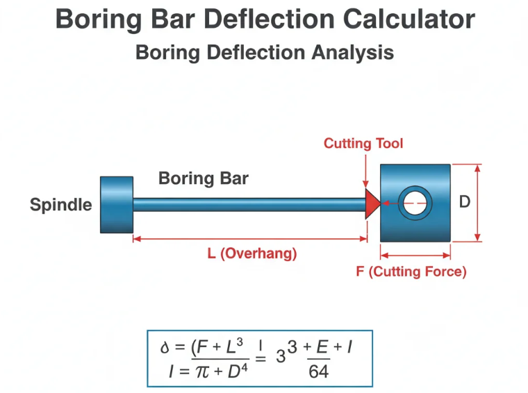
Minimize Tool Overhang: Cantilever deflection is proportional to the cube of overhang length ($\delta \propto L^3$). Every millimeter reduced yields exponential gains in rigidity.
-
Upgrade Tool Shank Material:
-
Standard Steel Shanks: Best suited for short overhangs ($L/D \le 4$).
-
Solid Carbide / Heavy Metal Shanks: Solid carbide features a modulus of elasticity ($E$) roughly 2 to 3 times higher than steel. For medium-length boring ($L/D = 4\text{--}6$), upgrading to solid carbide shanks dramatically improves bending resistance.
-
Strategy 3: Integrate Dynamic Damping and Phase Disruption
When overhang ratios increase to the point where physical stiffness alone can no longer suppress vibration, dynamic dampening techniques become essential:
-
Disrupt Vibration Frequencies: Use specialized internal mechanisms or vary cutting conditions to disrupt phase synchronization across consecutive cuts.
-
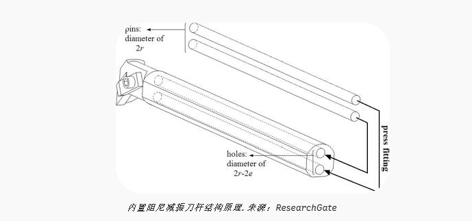
Deploy Passive Damped Boring Bars:
-
How They Work: Damped boring bars contain an internal "mass-spring-damper" mechanism suspended in heavy fluid inside the shank. As the outer bar vibrates, the internal mass resonates out-of-phase, absorbing dynamic energy and dissipating it as heat.
-
Ideal Applications: Deep-hole boring ($L/D > 6$) and chatter-prone thin-walled internal turning.
-
-
Strategy 4: Fine-Tune Parameters and Enable CNC Control Features
-
Adjust Spindle Speed and Feed Rate:
-
Shift spindle speed up or down by $10\%\text{--}15\%$ to find a chatter-free sweet spot outside local resonance lobes.
-
Slightly increasing feed rate ($Fn$) increases chip thickness, which can provide a stabilizing mechanical damping effect.
-
-
Enable Spindle Speed Variation (SSV):
Modern CNC systems (such as Fanuc, Siemens, and Haas) feature SSV modes. When activated, the control continuously modulates spindle RPM in a sine-wave pattern. This continuously alters chip thickness phase relationships, suppressing regenerative chatter at the source.
-
4. Anti-Vibration Tooling Selection Guide (By Overhang Ratio $L/D$)
Use this quick-reference table for immediate decision-making on the shop floor:
| Overhang Ratio (L/D) | Typical Machining Scenario | Recommended Tooling & Process Setup | Core Anti-Vibration Mechanism |
| $L/D \le 4$ | Standard OD turning / Shallow ID boring | Standard steel shank + sharp insert edge + small nose radius ($R0.4\text{ mm}$) + $90^\circ$ lead angle | Reduces radial cutting force |
| $L/D = 4 \text{--} 6$ | Medium-depth ID boring / Slender shafts | Solid carbide shank / Heavy metal shank + steady rest support | Increases static bending stiffness |
| $L/D > 6$ | Deep-hole boring / Complex thin-walled parts | Passive damped boring bar + CNC Spindle Speed Variation (SSV) enabled | Dynamically absorbs vibration energy + disrupts resonance phase |
Conclusion
Eliminating chatter in CNC turning requires a systematic approach rather than a single quick fix:
-
Start with Setup Basics: Minimize overhang, verify clamping stability, and clean tool seating faces.
-
Optimize Geometry & Parameters: Switch to sharp, small-radius inserts with high lead angles, and adjust speeds/feeds.
-
Upgrade Tooling for Rigidity: Upgrade to solid carbide or tuned-mass damped boring bars as overhang ratios ($L/D$) increase.
Applying this structured methodology eliminates surface chatter marks, restores part tolerances, and significantly extends the service life of both your cutting tools and machine tool spindles!
Flat-Bed vs. Slant-Bed CNC Lathe: What’s the Difference and Which One Do You Need?