
Creating Technical Drawings for CNC Machining
author: Yannis
2025-05-19

Cultivated in CNC Machine Industry for 20+ years.
Specializing in CNC Milling, Drilling, Turning, Tapping, and so on...
Self-created Brand LiSN for 10+ Years



Technical Drawing for CNC Machining
In the realm of modern manufacturing, CNC (Computer Numerical Control) machining has revolutionized the production process with its precision and efficiency. At the heart of successful CNC machining lies the technical drawing, a crucial document that serves as a blueprint for CNC machines. This blog will explore what technical drawings for CNC machining entail, their significance, key components, and how they guide the operation of CNC machines to create high-quality parts.
The Role of Technical Drawings in CNC Machining
A technical drawing for CNC machining is a detailed, standardized visual representation of a part or assembly. It conveys all the necessary information for CNC machines to accurately manufacture the intended component. Without a clear and precise technical drawing, CNC operators and programmers would lack the essential instructions to set up and operate the machines effectively.
Technical drawings act as a universal language between designers, engineers, CNC programmers, and operators. They translate abstract design concepts into tangible manufacturing instructions. For CNC machines, which rely on precise numerical data, technical drawings provide the specific dimensions, tolerances, surface finishes, and feature details required to produce parts that meet the exact specifications.
Types of Technical Drawings for CNC Machining
2D Drawings
Two-dimensional (2D) drawings are a traditional yet still widely used form in CNC machining. They present the part from multiple orthogonal views, such as top, front, and side views. 2D drawings use lines, symbols, and annotations to depict the shape, dimensions, and features of the part. Dimensions are clearly labeled with tolerances, indicating the acceptable range of variation for each measurement. For example, a 2D technical drawing for a CNC-machined metal bracket would show the lengths, widths, and heights of the bracket, along with hole diameters and their precise locations.
3D Models
Three-dimensional (3D) models have become increasingly popular in CNC machining. Created using Computer-Aided Design (CAD) software, 3D models offer a more intuitive and comprehensive view of the part. They can be rotated and viewed from any angle, allowing CNC programmers to better understand the part's geometry. 3D models can also be directly imported into Computer-Aided Manufacturing (CAM) software, which then generates the G-code programs for CNC machines. This seamless integration reduces the potential for errors that might occur during the transition from 2D drawings to machining instructions.
Key Elements of Technical Drawings for CNC Machining
Dimensions and Tolerances
Accurate dimensions are the foundation of any technical drawing for CNC machining. Every critical measurement of the part must be clearly specified, and tolerances define the acceptable deviation from the nominal dimension. Tight tolerances are often required in CNC machining, especially for parts used in industries like aerospace and medical devices. For instance, in a CNC-machined aerospace component, a tolerance of ±0.01mm might be specified to ensure a perfect fit and optimal performance.
Surface Finish
The surface finish of a part affects its functionality and appearance. Technical drawings indicate the desired surface finish using symbols and roughness values. Different CNC machining operations, such as milling, turning, or grinding, can achieve various surface finishes. A technical drawing for a CNC-milled automotive part might specify a surface roughness of Ra 0.8μm to ensure proper lubrication and reduced friction.
Geometric Features and Symbols
Technical drawings use a set of standardized geometric symbols to represent features like holes, slots, chamfers, and fillets. These symbols convey the shape, size, and location of the features clearly. For example, a circle with a cross inside it indicates a through-hole, and the diameter and depth of the hole are specified nearby. Understanding these symbols is essential for CNC programmers and operators to correctly interpret the drawing and program the CNC machines.
Creating Technical Drawings for CNC Machining
The process of creating technical drawings for CNC machining begins with the design concept. Designers use CAD software to create either 2D drawings or 3D models. When creating 2D drawings, they carefully select the appropriate views to display all the necessary details. For 3D models, they build the part's geometry accurately, taking into account all the design requirements.
After the initial design, the drawings are refined to include all the machining - relevant information, such as dimensions, tolerances, surface finishes, and geometric symbols. Once the technical drawing is complete, it is reviewed by engineers to ensure its accuracy and compliance with manufacturing standards. Finally, the drawing is passed on to CNC programmers, who use it to generate the G-code programs that will guide the CNC machines during the machining process.
Common Challenges and Solutions in Technical Drawings for CNC Machining
One common challenge is ensuring the clarity and comprehensibility of the drawing. Ambiguous or unclear dimensions or symbols can lead to errors in CNC programming and machining. To address this, designers should follow strict drawing standards and use clear, concise annotations. Another challenge is keeping the technical drawing up to date as the design evolves. Regular reviews and revisions are necessary to ensure that the drawing accurately reflects the current design and manufacturing requirements.
Conclusion
Technical drawings are an integral part of CNC machining, providing the detailed instructions that CNC machines rely on to produce accurate and high-quality parts. Whether in the form of 2D drawings or 3D models, these drawings convey essential information such as dimensions, tolerances, surface finishes, and geometric features. By understanding the role, types, key elements, and creation process of technical drawings for CNC machining, manufacturers can optimize their production processes, reduce errors, and achieve better results in the highly precise world of CNC manufacturing.


Heat Treatment for CNC Machined Parts
Conversion Coatings for Metal and Plastic Parts
Related Article
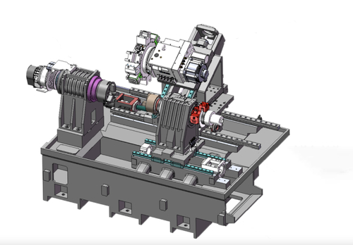
Compare flat-bed and slant-bed CNC lathes by thermal stability, rigidity, guideways, and production needs. Explore practical examples and a buying checklist to choose the right machine for your workshop.
Flat-Bed CNC Lathe vs Slant-Bed CNC Lathe: A Practical Buying Guide
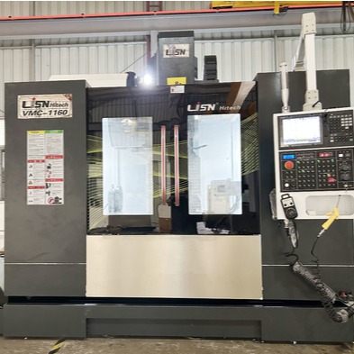

Preventing casting defects is crucial for efficient CNC machining and high-quality final products. Understanding causes and taking precautions boosts casting quality, enhances CNC performance, and gives manufacturers a competitive edge.
You are worth collecting the causes and precautions for six common defects of the casting
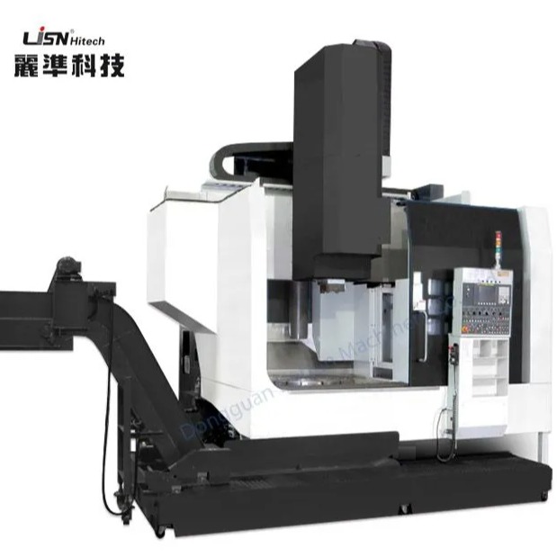
A CNC Milling Machine is a computer-controlled machine tool that removes material with rotating cutting tools to produce high-precision parts. It is widely used to machine aluminum, steel, stainless steel, titanium, brass, plastics, and other materials. Typical applications include aerospace components, automotive parts, medical devices, mold and die, robotics, electronics, and custom industrial components with tight tolerances and complex geometries.
CNC Milling Machine Buyer's Guide (2026)